Introduction to PDF of Basic Electronics
In this pdf book, you’re going to learn the basics of electronics. It will give you the strong foundation you need to create electronic projects.
This pdf of basic electronics, Practical Electronic Circuits: A Strong Foundation for Creating Electronic Projects is designed to provide skills and a hands-on practical experience for students of electronic engineering and computer science. It also provides a good foundation for anyone interested in learning how to create electronic projects.
Electronics curricula are densely packed in many engineering and computer science colleges. This pdf book therefore is a great help because it treats each topic thoroughly. It is also a great companion.
The book will be of great help for your electronics education because it is filled with simple and moderately complex practical projects. Links to stores where you can get very cheap electronic parts to work with are also included.
You will also learn how to be safe in your workspace, and how to develop the courage you need to carry out any electronic project. A step by step approach is used to explain the process of carrying out an electronic project.
This book is also a great value for every electronics students undergoing technical training. It encourages them through providing useful technical advice needed in a highly practical environment, with a clearly defined problem so they do not get stuck while building even complex projects.

1. Fundamentals of Electronic Circuits
1.1 Power Supplies & Electronic Signals
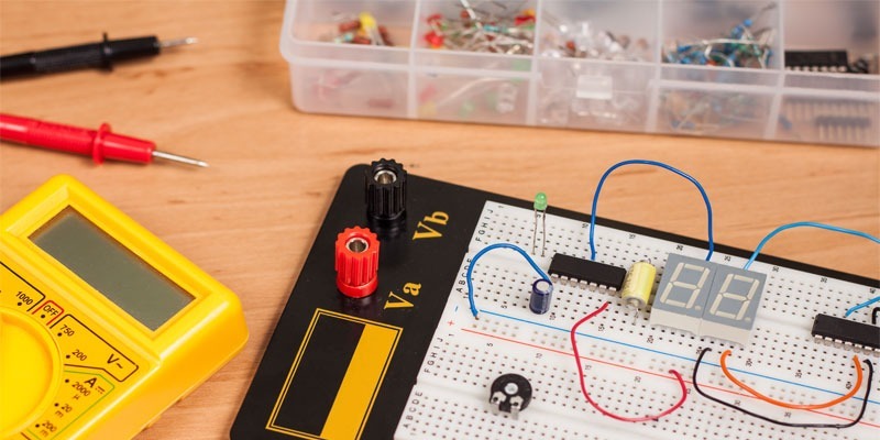
In this chapter, I lay some important groundwork that you need to make sense of the rest of the book. I examine the bits and pieces that make up the most common types of electronic devices, and that make electronic circuits in general to work.
All electronic and electrical devices, from the simplest flashlight to a giant and complex control systems on a modern aircraft, all need one thing in common: power supply.
1.1.1 Power Supply in Pdf of Basic Electronics
A power supply is a source of electricity, or more precisely, a source of electrons. Without power supply, an electronic device is all just a pile of inactive plastic, metal or silicon (among other things).
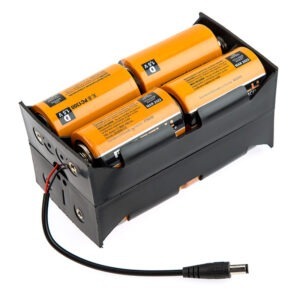
A few examples of power supplies are batteries, power adaptors for charging your mobile phones and laptop computers and so on. Fig. 1.1.1 shows a power supply built by assembling a few batteries.
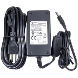
However, a power supply itself can be built with electronic devices, such as shown in Fig. 1.1.2 and Fig. 1.1.3.

Next, I take a look at the basic concept underlying all electronic circuits: signals. I’m not going to bore you with any complicated or tedious or physics concepts, but I want to warn you from the start.
In order to learn how electronic circuits work and get to a level where you can design and build your own electronic devices, you need to have at least a basic idea of what a signal is. So put on your thinking cap and come with me.
Fig. 1.1.4 shows various symbols used for representing DC and AC power sources in electronic circuits. The positive terminal of a DC power supply is usually represented by “+” while the negative terminal is represented by “─‘’.
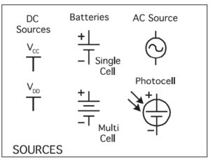
As shown in Fig. 1.1.4, the + terminal of bi-polar junction transistor circuits is often represented by VCC, while the + terminal of FET and MOSFET circuits is often represented by VDD. We will look at FET (field effect transistor) and MOSFET (metal-oxide-semiconductor transistor) circuits later.
1.1.2 Electronic Signal
In the field of electronics, a signal is an electric current or electromagnetic field used to transmit data from one place to another.
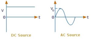
DC (Direct Current) is the simplest form of signal because it travels in only one direction so it can be switched on or off. It is the principle behind the working of the early telegraph.
AC (Alternating Current) on the other hand is a type of current that pulsates or changes direction periodically. Electronic devices process AC signals very often. Such signals are electromagnetic carriers of one or more data streams. Fig. 1.1.5 shows graphical representations of DC and AC signals.
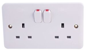
A very common source of alternating current is the mains, which is usually obtained from the electric sockets on the walls of your room or office. Mains is usually supplied by the electric power authority in your locality. Fig. 1.1.6.
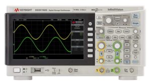
Before I move on to the next section, I must mention that the oscilloscope is a very good example of both DC and AC signal sources often used in electronics labs. See Fig. 1.1.7. You will learn how to use the oscilloscope later.
1.2 Electricity: Charges & Current
Even though we don’t know exactly what electricity is, we do know a lot about what it does and how it behaves.
You will find it easier to understand electricity if you avoid using the term electricity itself to describe it. The reason is very simple: The word electricity is not very precise. Scientists and engineers use the word electricity to refer to a few different but related things.
The most common ones are rather precise names like electric charge, electric current, electric field, and electric energy. All these are what are commonly called electricity.
1.2.1 Electric Charge
Electric charge, electrical charge, electrostatic charge, or simply charge, is the characteristic of a unit of matter that expresses the extent to which it has more or fewer electrons than protons.
In an atom, it is the electron that carries a negative elementary or unit charge and the proton carries a positive charge. The two types of charge are equal and opposite.
For practical purposes, the most important thing you should know about electric charge is that opposite charges attract and similar charges repel. In other words,
- negative charges attract positive charges
- positive charges attract negative charges
- negative charges repel negative charges
- positive charges repel positive charges
Therefore an electron and a proton attract each other, but an electron repels another electron and a proton repels another proton. The unit of electric charge is coulomb (symbol is C).
1.2.2 Electric Current
An electric current is defined as the rate of flow of electric charge past a given point or region. We say an electric current exists when there is a net flow of electric charge through a given point or region. In electric circuits this charge is often carried by electrons moving through a wire.
In other words, electric current is the total charge that passes through a given cross-sectional area A per unit time. This cross-sectional area is frequently represented by a slice through a solid material, such as a conductor (for example, a copper wire).
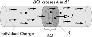
Supposing ΔQ represents the amount of charge that passes through an area in a given time interval Δt as shown in Fig. 1.2.1., then the average current Iave is defined as:
The SI unit (international system of units) of current is therefore coulombs per second or C/s, but the ampere (A) is often preferred.
So 1 A = 1 C/s.
The ampere is a rather too large a unit for practical uses in electronic circuits, so you will find it more convenient to express current in milliamps (mA), microamps ( A) or nanoamps ( A).
1 mA = 1 × 10⁻³ A,
1 μA = 1 × 10⁻⁶ A,
1 nA = 1 × 10⁻⁹ A.
1.2.3 Current Drawn By Common Electronic Devices
When tinkering with circuits in general, it is good to have idea of how much current common electronic and electrical devices (commonly called loads) draw from their power supplies. Below are some examples:
- A 100-watt lightbulb (electrical device): about 1 A;
- A laptop computer (electronic gadget): between 2 to 3 A;
- A microwave oven (electrical device): about 10 A;
- A fluorescent light: 1 to 2 A;
- A radio or stereo set: (electronic): 0.5 to 3 A;
- A typical LED (a small electronic indicator light): 20 mA;
- An microchip (electronic): a few μA or even perhaps several pA
- A current sufficient to induce a cardiac or respiratory arrest: about 100 mA to 1 A.
- A mobile (smart) phone: around 200 mA
- An electric fan (electrical device): about 1 A;
- A TV set (electronic gadget): 1 to 3 A;
- A toaster (electrical gadget): 7 to 10 A;
- An automobile starter: around 200 A;
- A lightning strike: about 1000 A.
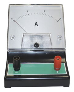
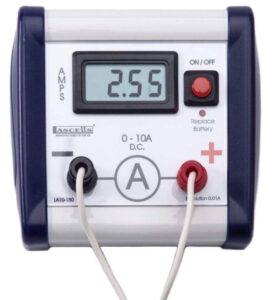
Electric current can be measured by a ammeter but a digital multimeter is often used in electronics because it has higher precision and can measure various ranges of current. We will look at the multimeter and how to use it in chapter 7.
In electronic circuits, an ammeter is represented by
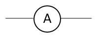
Fig. 1.2.2 shows an analogue DC ammeter and Fig. 1.2.3 shows a digital DC ammeter.
1.3 Electric Voltage, Grounds & Power in Pdf of Basic Electronics
1.3.1 Electric Voltage
In their natural state, the electrons in a conductor such as a copper wire freely move from one point to another, but in a completely random way. To make them all move together in one and the same direction, all you have to do is give them a push. In other words, electric voltage can be thought of as a kind of “electrical pressure”.
The technical term for this push is electromotive force, abbreviated EMF, or sometimes simply E. But it is more commonly known as voltage. Technically speaking the voltage is also referred to as a potential difference or just potential —they both mean the same thing. This means that potential difference or voltage is a relative word since you can only measure it across two points, one of which may the reference point called ground.
For example, if we say that a point in a circuit has a voltage of 12 V it is meaningless unless we have another point in the circuit (which may be the ground) with which to compare it.
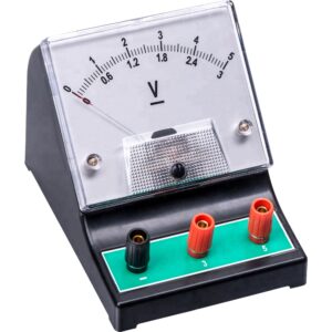
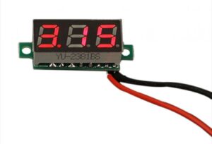
Electric voltage can be measured by a voltmeter but a digital multimeter is often used in electronics because it has higher precision and can measure various ranges of voltage.
In electronic circuits a voltmeter is represented by
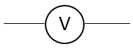
Fig. 1.3.1 shows an analogue DC voltmeter and Fig. 1.3.2 shows a digital DC voltmeter.
1.3.2 Grounds
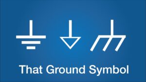
As we discussed in the last section voltage is a relativity game. Very often we have to define a ground. So a ground is a zero-volt (0-V) reference point in a circuit on which to base all other voltage measurements. The ground is frequently represented by one of the three symbols shown in Fig. 1.3.3.
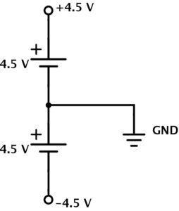
Note that we can have a point in a circuit that is below the ground, that is, that has a negative voltage. For example, Fig. 1.3.4 (connection of two cells in series) shows one way in which we can define voltages by selecting a ground—which in this case is simply the middle GND ( a 0-V reference marker).
The upper point (+4.5 V) is above the ground so it is positive, while the lower point (-4.5 V) is below the ground so it is negative.
1.3.3 Electric Power
Another important electrical quantity is power. Power is simply the work done by an electric circuit. Electric current itself is not all that useful. It becomes useful only when the energy it carries is converted into some other form of energy, such as heat, light, sound, or radio waves.
Let us take an incandescent light bulb as an example. The voltage pushes current through the filament, which converts the energy carried by the current into heat and light.
So we now have a kind of generalized power law, which says that if the current entering a device and the voltage across it can be measured, the power used by the device is given by:
P = VI (Voltage multiplied by current)
Power is measured in units called watts (abbreviated W ).
1.3.4 Electric Heat
The power consumed or dissipated by an electronic device or an appliance can be converted to heat energy, as we saw in the previous example of an incandescent light bulb. In other words, power can be lost into heating in an electronic component or device.
It is often a very important part of circuit design to know how to calculate the power dissipated by a circuit. That is because electronic components like transistors, resistors, capacitors and integrated circuits (which we will discuss later) all have some maximum power ratings.
If you exceed the maximum power rating of an electronic component, you run the risk of burning it. For example using a 1/4 -watt resistor in a circuit that dissipates 2 watts will cause the damage of the resistor.
1.4 Conductors, Resistors & Semiconductors
1.4.1 Conductors, Insulators & Resistivity
An electrical conductor is a material that conducts electricity. Electrical conductivity is the ability of a material to conduct electricity. An insulator is a material that does not conduct electricity.
1.4.2 Electrical Resistance & Resistivity
Electronics is all about manipulation of the flow of electric current. One of the major ways of manipulating current is by using resistance to reducing it. If there was no resistance, flow of current would be unregulated and useless.
The electrical resistance (R) of an object or material is a measure of how much it opposes the flow of electric current. The SI unit of resistance is ohm (Ω). The object or material is called a resistor.
Conductance (G) is the inverse of resistance. The SI unit is Siemens, S although mho can also be used as alternative unit.
Resistivity (ρ) is the resistance of a conductor of a unit cross-sectional area and a unit length. Theoretically, resistivity is very useful for comparing the ability of various materials to conduct electric currents. Therefore a conductor with a high resistivity is a poor conductor. The SI unit of resistivity is ohm-meter (Ωm).
The value of resistivity of a conductor depends on its temperature. For practical purposes, resistivity values are usually tabulated at a temperature of 20° C (68° F). The resistivity of a metallic conductor generally increases with a rise in temperature. However, for semiconductors like silicon and carbon, the resistivity generally decreases with temperature rise.
For example, the resistivity of a very good electrical conductor like a hard-drawn copper wire is 1.77 × 10⁻⁸ ohm-meter at 20° C.
1.4.3 Conductivity
Conductivity (σ) is the reciprocal of resistivity, and is a measure of how much electric current flows in a conductor. The SI unit of conductivity is Siemens per meter (or mho per meter).
A good electrical conductor has high conductivity but a low resistivity. A good insulator (also known as a dielectric), has a high resistivity but a low conductivity. Semiconductors have intermediate values of both.
1.4.4 Good Conductors, Poor Conductors & Semiconductors
A good electrical conductor allows flow of electric current with little or negligible impediment. A Examples of good conductors are metals such as silver, copper and aluminum. Carbon is also a very good conductor.
A poor or bad electrical conductor on the other hand is a material that does not readily conducts electric current. Steel, tungsten and bismuth are examples of poor conductors because it is an alloy.
Insulators are materials that are poor conductors of electricity.
Some examples of good insulators are plastic, glass and Teflon. The most important factor that determines if a material is a conductor or an insulator is how readily its atoms give up the electrons on their outermost shells. Many atoms are very possessive of their electrons, and are therefore good insulators.
To enjoy the rest of this pdf of basic electronics, please consider ordering this book. To continue, please click the button below.